
Why Piping Design is a Very Good Career Option for Mechanical Engineers ?

Become a Piping Design Engineer, Change your life forever.
Dear Mechanical Engineer
I am Gijo Vijayan here, former Mechanical Engineer (Piping Design) from Reliance Petroleum Ltd. I am going to give you some important information that can change your life forever. I passed out from MA College of Engineering, Kothamangalam, Kerala in 1996.

I am writing the blog to create awareness among Mechanical Engineers who does not have any idea or guidance regarding their career. Piping Design is a very good career option for Mechanical Engineers who are good at drawings and has strong analytical skills.
If you are a Mechanical Engineer interested to learn Piping design, Call/Whatsapp: +91 9798404042. Email: gijo@gijokv.com
Once you acquire relevant skills in Piping design, you can have fabulous career in Piping Design. You can get jobs in Oil and gas, Power, Nuclear, infrastructure sectors etc.
The salary levels are also high. You must come into piping design only if you are interested in detail engineering. You need to have high IQ and memory to become a successful Piping Engineer.
I worked as an apprentice at Kochi Refineries Ltd, in 1997 and then in 1998 I was selected as a “GET” (Graduate Engineer Trainee) by the largest Oil and Gas company in Private sector in India, Reliance Petroleum Ltd. I worked in “Reliance” from 1998 to 2005, then I started my own business in Recruitment and Piping Design Consulting.
Every year thousands of Fresh Mechanical Engineers are passing out from hundreds of Engineering colleges all over India. Most of these students do not have the right skills and career guidance, and they end up working in factories, construction companies for low salaries.

When I passed out B.Tech in Mechanical Engineering in 1996, I was literally thrown to the streets with no guidance whatsoever. Students are puzzled and confused what to do next. To such students, I am here to give you guidance based on my experience in the past.
The first thing that you need to do is not to panic. You need to remain calm. Try to analyze your skills and find out which filed is most suitable for you. I have the following suggestions for you.
If you are good in Machine drawing, GD (Geometric Drawing), try to go into a career in detail engineering. Piping Design and CAD/CAM modeling are the best options.
If you are good in Marketing and interacting with people, try to get a job in sales and marketing of Mechanical products, Machines, other things etc.
If you want to relax with your family 6 months, and work next six months, make lot of money, go into shipping Line and become a Mechanical Engineer with Merchant Navy. There are many companies in Ballard estate, Mumbai who can take you as trainee after undergoing training in Marine engineering.
If you love Robots, learn Python language and get into coding for Robots. There is huge opportunity in Japan for Robotics programmers; You need to learn Japanese Language.
Why not become a Piping Design Engineer?
I worked in “Reliance” in construction field for 2 years, then I worked as a Piping Designer. It was an exciting opportunity. In the year 2000, I worked in a software called — PDS (Plant design System) by Intergraph, now this software is called S3D (Hexagon Company). This software is used in 3D design and modeling of Piping for Process plants, oil refineries etc.
Two 17 inch monitors were placed before me and I was trained to work in PDS. I was asked to route the pipe through structures and I can see the elevation, plan, section, side view of Piping design using these 2 monitors.
I worked with a large team of people in Reliance in Piping Design. There were experts and most of them had very good salary also.
I was exposed to the following Piping Design Standards in Reliance. Following were the codes and standards that I was introduced to.
ANSI — American National Standards Institute — ANSI provides a forum for development of American national standards
ASME — American Society of Mechanical Engineers — ASME is one of the leading organizations in the world developing codes and standards
ASME — Performance Test Codes — The ASME Performance Test Codes provide standard directions and rules for conducting and reporting tests
ASME B31 — Pressure Piping — A survey of one of the most important pressure pipe codes — ASME B31, earlier known as ANSI B31
CSI Master Format Specifications — Construction Specifications Institute’s 2004 Master-Format Edition
DIN — Deutsches Institut für Normung — DIN — the German Institute for Standardization
ISO — International Organization for Standardization — ISO — the International Organization for Standardization
ISO — Pipe, Tube and Fittings Standards and Specifications — International Organization for Standardization — ISO — pipe, tube and fittings standards and specifications.
There are thousands of codes and standards in Piping for each application, following is the summary:
ASME — American Society of Mechanical Engineers (ASME)
ASME Codes for Piping Industry
1.0 ASME B31: Code for Pressure Piping
ASME B31.3 — Process Piping Code
ASME B31.1 — Power Piping Code
ASME B31.4 — Pipeline Transportation Systems for Liquids and Slurries
ASME B31.5 — Refrigeration Piping and Heat Transfer Components
ASME B31.8 — Gas Transmission and Distribution Piping Systems
ASTM Standards — The American Society for Testing and Materials (ASTM)
API Standards — The American Petroleum Institute (API)
What are the skills needed to become a Piping Design Engineer?
2D — Software
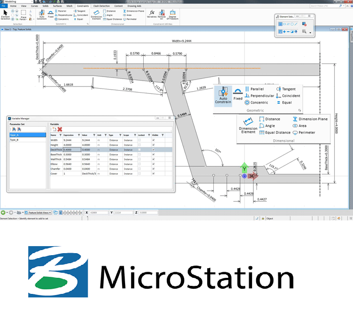
Autocad, Microstation
Top 3D Piping Design Software Programs are
SP3D by Hexagon.
E3D/PDMS by AVEVA.
AutoPLANT 3D by Bentley.
AutoCAD Plant 3D by AutoDESK.
CADWorx Plant Professional by Hexagon.Stress Analysys:
CAESAR — II — For stress Analysis
Piping design is an excellent career option for Mechanical engineers, it is not suitable for everyone. If you love design engineering and love imagination and creativity, piping design field will suit you lot. If you never like design engineering, please do not purse this option as a career.
AVEVA — PDMS
As a Fresh Mechanical Engineer, How to enter into Piping Design Field?
As a Experienced Piping Design engineer, I want to point out the biggest mistakes that Mechanical Engineers do while trying to learn piping design and enter into the field.
Start with basics of Piping Design.
I have seen many Mechanical engineering students who wants to become Piping design engineers start learning the software without knowing the fundamentals of the same. Never do that.
You need to start studying the basics of Piping designs, codes and standards first. Then only learn the software. Else you will not understand many things while you read the drawings.
Piping Design fundamentals include the following.
Piping and Instrumentation Diagrams (P&IDs)
P&ID symbols and terminologies
Piping codes
Piping specification
Piping isometrics
Fabrication isos and bill of materials
Three dimensional (3D) models
Components of a Piping System
Fittings
Flanges
Valves
Material classification system and specifications
Piping Fabrication and NDT

Always remember that Piping design is a vast field with lot to learn. It may take 10 years for anyone to become a full fledged Piping Design Engineer. One should not learn the software without having ample knowledge of Piping design basics, P&ID symbols, codes and standards, material specifications etc. You should be able to read P&ID diagrams as well as Piping Isometric diagrams with ease. After you gain sufficient knowledge in basic piping design, then only you must learn the 2D & 3D softwares in Piping Design.
Always remember that the codes and standards for various industries such as oil and gas, Power, Nuclear, Infrastructure etc are different, but the fundamentals of Piping design remains the same.
Piping and instrumentation diagram
A piping and instrumentation diagram is a detailed diagram in the process industry which shows the piping and process equipment together with the instrumentation and control devices. A piping and instrumentation diagram, or P&ID, shows the piping and related components of a physical process flow. It’s most commonly used in the engineering field. P&ID is indispensable as transmitters of information, essential in the design stages. It can also be considered as the instruments of communication. In the final analysis, process diagrams communicate an astonishing amount of engineering information about many things to many groups for a variety of uses
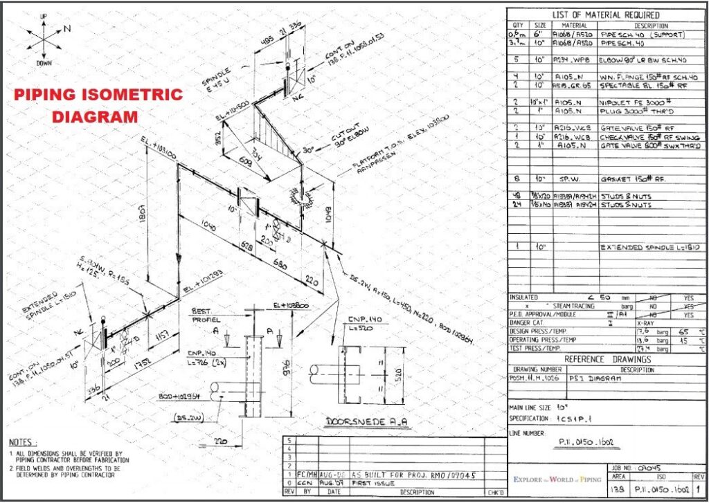
Piping Isometrics
What to include in piping isometric drawing?
A piping isometric drawing provides all the required information like:
Pipe Line Number.
Continuation isometric number.
Flow direction.
Piping dimensions.
Piping joint types, weld types.
Flange and valve types.
Equipment connection details.
Piping and Component descriptions with size, quantity, and material codes.
Piping Material Specifications
There are hundreds of materials used in Piping Design. Each is described by a specific code. The material specification varies from industry to industry and application to application.
What is the difference between piping engineer and piping designer?
Piping Engineer is a generalized term for following 3 sub branches
Piping Layout Engineer (3D/2D)
Piping Stress Engineer
Piping Material Engineer
On the other hand a Piping Designer falls under the first category (Layouts).
From what I have seen, a piping designers first designs the piping, and the work is later checked and validated by an experienced Senior designer or an experienced Piping engineer.
From what I have seen, interdisciplinary communications and complex calculations are performed by a Piping Engineer.
But trust me, these definitions vary slightly as per different company cultures and organizational structure.
What is S 3D (Former Smartplant 3D) ?
SP3D (Smart Plant 3D) is a modeling software program used for pipe designing. It allows all disciplines to work simultaneously in one relational database, where all modifications are shared with all users in real time. It is a data-centric and rule-driven solution that is used for streamlining engineering design processes while preserving existing plant data and making it more usable. SP3D Training can be an opportunity for you to increase your chances of working in various sectors, like power plants, petrochemicals, paper plants, corporate buildings, pharmaceutical plants, food and beverages, water treatment facilities, and environmental waste disposal. You will learn the techniques and tools related to piping, making designing easier and simpler for you.
SmartPlant 3D is the industry’s most advanced, most productive next-generation 3D design system for the process and power industries including automated design capabilities.
Smart® 3D — a next generation, data-centric, and rule-driven solution — is specifically designed to deliver mission-critical requirements. Breaking through barriers imposed by traditional technologies to enable a truly iterative design environment, Smart 3D provides a competitive edge to EPCs and owner operators alike.
A fundamental component of SmartPlant® Enterprise, Intergraph Smart 3D provides all of the capabilities needed to design plant, marine, and materials handling facilities, and then maintain their 3D “as-built” representations. Take advantage of data-centric technology, a strong rules- and relationship based architecture, customized automation capabilities, and an integrated reuse approach to execute even the largest and most complex projects with centralized visibility and control.
Key benefits:
Real-time Concurrent Design :
Leverage the datacentric 3D modeling paradigm to maximize project communication and efficiency through real-time concurrent design.
Intelligent Rules and Relationships
Capture your company’s tacit knowledge and engineering expertise to drive 3D design with customizable rules that enable objects to interact in an intelligent and automated manner.
Task-based Modeling
Ramp up projects quickly with a common, easy-to-learn interface that also provides a discipline-specific experience for each user based on the task/workflow being executed.
Automated Deliverables
Ensure accuracy of procurement, fabrication, and construction packages as well as adherence to project schedule via fully automated drawing and report generation.
Interoperability
Work with a rich array of 3D design formats in a single hybrid model while consistently sharing engineering data across multiple teams via integration with SmartPlant Enterprise.
SMART 3D WAS THE CLEAR MARKET LEADER. WHILE OTHER 3D SOLUTIONS FOCUS ON SIMPLY ACHIEVING DESIGN, SMART 3D ENABLES OPTIMIZED DESIGN, WHICH MEANS IT INCREASES ACCURACY AND EFFICIENCY, AND SHORTENS PROJECT SCHEDULES.
Leading Edge Technology
Single Application
Smart 3D provides multi-industry capabilities in a single application. Combining the functionality for ship/offshore projects and materials handling with those of onshore plant design.
Model Data Reuse
Extended Model Data Reuse (MDR) capabilities now support marine structural objects, pipe spec mapping, and drawing reuse.
Productivity Improvements
Improved performance and reduced administrative overhead for global workshare for Oracle users via Oracle Golden Gate.
Full Integration
Full integration of Intergraph’s powerful Batch Services technology, including central administration of both local and piped queues.
New Capabilities for Onshore Plant Design
Several powerful application environments are now available including modular design capabilities, weight and center of gravity, automated structural detailing, structural manufacturing, hole management, and additional automatic drawing extraction capabilities.
3D Interoperability
Smart 3D is the only system to offer interoperability with both graphics and data attributes of foreign CAD models, making it ideally suited to brownfield and joint-venture projects.
Drawings and Reports
Improvements to automated generation of project deliverables — including simplified administration and configuration utilities — add value to projects more quickly than ever before.
Marine and Offshore
Enhancements include sophisticated plate-splitting and weld generation capabilities, advanced member placement, parametric modeling of topological openings, additional options for structural detailing, and greater detection and change management capabilities in the Common Parts Engine.
Mining and Materials Handling
Smart 3D now leverages a conveyor belt object class, extending capabilities to model, manage, and generate accurate and detailed deliverables on mining projects in a comprehensive and efficient manner.
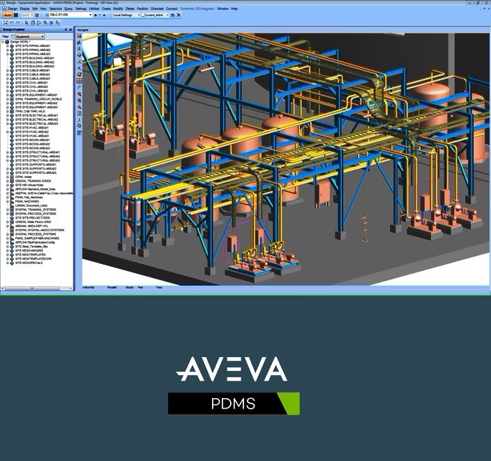
AVEVA PDMS
Developed by AVEVA, Plant Design Management System software is used for analyzing the approach practically. The 3D CAD in the PDMS is a customizable software for construction and engineering projects. Delivering season through AVEVA PDMS builds the skill in the students to develop 3D plant design for all sizes of plant projects, ranging from minimal up-gradation to new installations of unlimited complexity.
PDMS is a 3D modelling software for modelling civil structures, process equipments and piping networks as well as various electrical and instrument components. Here is a list of shortcuts to help you increase your productivity in PDMS.
AVEVA PDMS is gradually being phased out and will be removed from the market by 2024 when it will be replaced with our latest, most advanced 3D design software ever, AVEVA™ E3D Design
#pipingdesign #mechanical #oilandgas #engineering #India #PIPING #pdms #sp3d